
CIS-75 Home http://www.c-jump.com/CIS75/CIS75syllabus.htm
Discussion:
Static model view of software architecture: class relationships.
Dynamic model view of software architecture: objects and messages.
Defines the structure (architecture) of the software system in terms of
classes connected by (involved in) relationships.
The Static Model uses:
class diagrams
class specifications.
Defines the behavior of the software system in terms of
objects cooperating with each other by exchanging messages
and providing services in order to solve the problem.
The Dynamic Model uses:
sequence diagrams
state diagrams
activity diagrams.
Model scenarios.
Model interaction of objects in the context of a particular activity.
Can be used to model use cases.

UML defines several forms of interaction diagrams:
sequence diagram (most common)
good at describing the behavior of several objects inside a single use case
state diagram
good at describing the behavior of one object across multiple use cases
activity diagram
good at showing the general sequence of activities for several objects and multiple use cases
Typical sequence diagram captures the behavior of a single scenario.
Thus, sequence diagram shows possible implementation of one scenario.
Sequence diagrams show the interaction as follows:
Each participant has a lifeline that runs vertically down the page
The ordering of messages sent accross object lifelines is interpreted by reading down the page.
Each lifeline has an activation bar that shows when the participant is active in the interaction.
Return arrows (optional) show values returned from the call.
In most cases sequence notation is self-explanatory.
Bottom line: good diagram should be readable by all indended audiences.
Participant names are specified in format
name : Class
where both name of the object and its Class are optional.
Note: You must keep the colon if using the class name.
Note: in UML 2 objects are shown without the underline.
Activation bars are optional in UML, but extremely valuable in clarifying the behavior.
Sequence diagrams show some extra notation for creating and deleting participants.
To create a participant, draw the message arrow directly into the participant box.
A message name is optional if using a constructor, typically marked with new.
Deletion of a participant is indicated by big X.
A message arrow going into the X indicates one participant explicitly deleting another.
An X at the end of a lifeline shows a participant deleting itself.
In a garbage-collected environment, program does not delete objects directly, but it's still worth using the X to indicate when an object is no longer needed.

Order item sequence diagram example:

Object A can access object B if:
A has a relationship with B.
Class of A has a static relationship with B.
A has a relationship with C, and C has a public relationship with B.
(Also consider static, friendly, and protected variants.)
A obtained a reference to B as an actual parameter to the currently executed method...
...for duration of this method only.
A created B,
only within the local scope,
while holding reference to B.
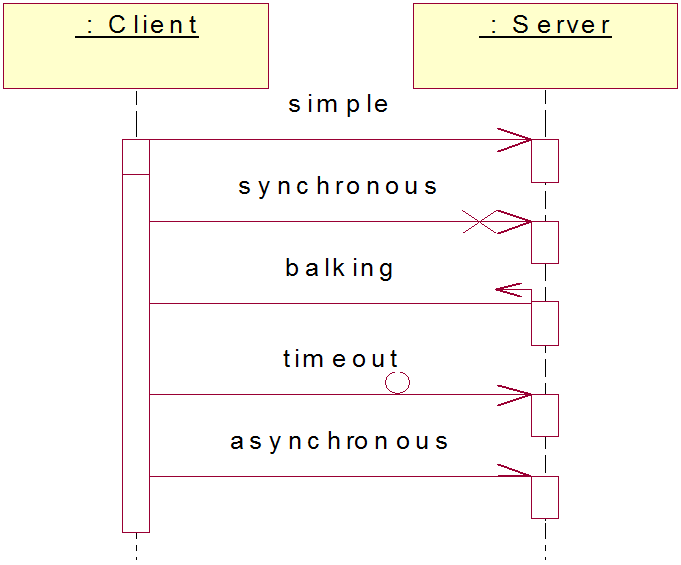
Note: balking messages are timeout-capable.
If a caller sends a synchronous message...
...the caller must wait until the message is done.
For example: invoking a subroutine.
If a caller sends an asynchronous message...
...the caller can continue processing: no need to wait for a response.
For example: multithreaded applications and message-oriented middleware.
Asynchrony
gives better responsiveness
reduces coupling
but is much harder to debug.
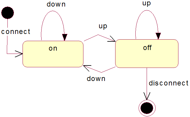
State machine formalizes the dynamic behavior of objects.
State machines are modeled by state diagrams in UML.
State diagrams should be provided for objects with interesting dynamic life cycles.
Various forms of state diagrams have been around since the 1960s.
Earliest object-oriented techniques adopted state diagrams to show behavior.
In object-oriented approaches, state machine diagram for a single class show the lifetime behavior of a single object accross multiple use cases.
State Diagrams are typically provided when:
objects are created and destroyed during the run-time.
objects accumulate the values of their attributes over their lifecycle.
objects represent equipment with a distinct operational cycle.
objects are constructed in stages.
objects represent requests, or tasks to be done.
objects are involved in dynamic relationships (in and out of relationships.)
State diagrams are good at describing the behavior of an object across several use cases.
State diagrams are not very good at describing behavior that involves a number of objects collaborating (think sequence diagrams instead.)
Not everyone finds state diagrams natural - remember to use the mix of techniques that works for your team/audience.
Do not draw state diagrams for every class in the system...
...use state diagrams only for classes that exhibit interesting behavior...
...UI and control objects often have the right kind of behavior for a state diagram.
Set of states S:
each state represents a specific stage in the lifecycle of an object.
Set of events E:
each event represents an incident, information that something specific has happened.
Transitions:
S × E -> S
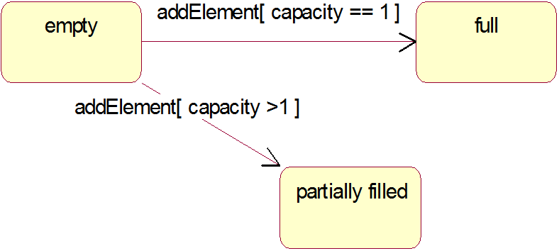
Each transition specifies the new state of the object...
...after it received a particular event in particular state.
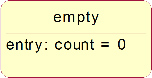
Actions: each action specifies the activity that must take place
when the object transitions to a particular state (one action per state.)
Creation states: object starts to exist.
Final states: object becomes dormant, or ceased to exist.
Other states: object in the midst of its lifecycle.
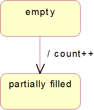
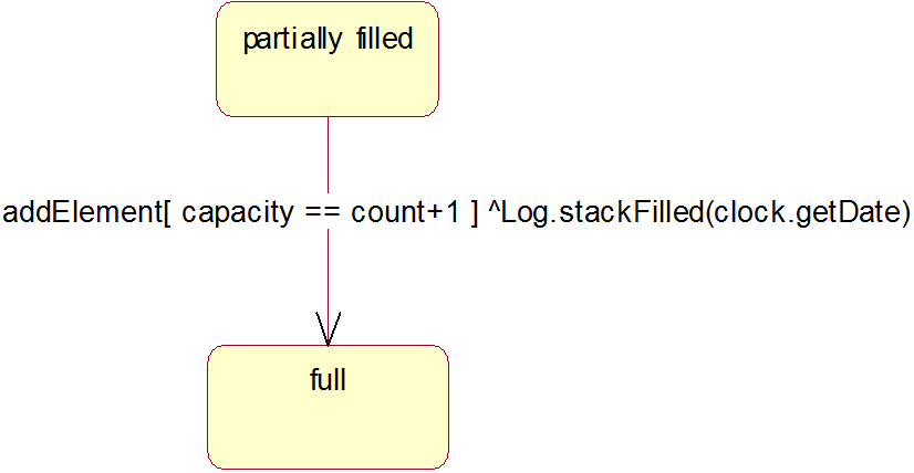
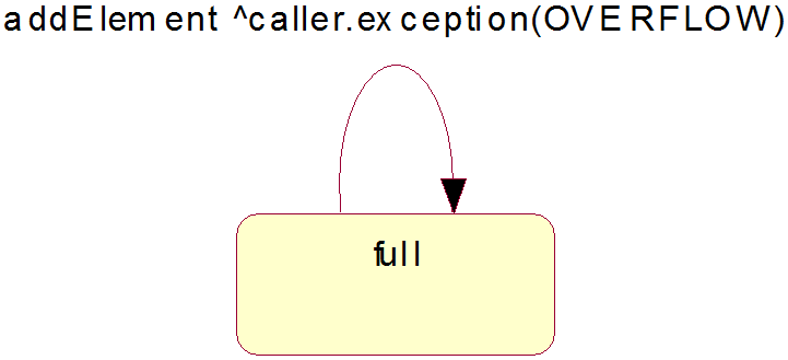
State transition arrows will indicate a movement from one state to another.
Transition label indicates a single event that triggers a potential change of state.
|
|
|
|
|
|
|
|

Activity diagrams are a technique to describe
procedural logic
business process
work flow
Similar to flowcharts, but the principal difference is notation that supports parallel behavior.
Process Order can serve as an example of a simple activity diagram:

Initial node shows where the activity begins.
A fork has one incoming activity flow and several outgoing concurrent flows.
In the Process Order example, Fill Order, Send Invoice, and their subsequent actions occur in parallel.
That is, those activities may occur in any order, or at the same time. In computer architecture, independent threads of execution can do things in parallel.
A join has a single outgoing flow which can proceed only when all of the incoming flows reach the join.
Conditional behavior is delineated by decisions and merges.
A decision (also called branch) has a single incoming flow and several guarded out-bound flows.
Each outbound flow has a guard: a Boolean condition placed inside square brackets.
Thus, a guard on the decision can be true or false.
Activity can take only one of the outbound flows: the guards are mutually exclusive.
Using [else] as a guard indicates that its flow used if all other guards are false.
A merge has multiple input flows and a single output.
A merge marks the end of conditional behavior started by a decision.
Activity diagrams say what happens, not who does what.
This means that the diagram does not specify which class is responsible for individual actions inside activity.
To contemplate the problem, activity diagrams can be partitioned into swim lanes, or even a grid-like dimensions, and further, nested grids with hierarchical rows and/or columns.
Note: activity diagrams aren't the most widely used UML technique at the moment; therefore, it is best to use more of swim lane partitions, and less of the grids.
Process Order activity partitioned into three swim lanes:

Typical uses:
UML-compliant flowcharts (decision branches and merges)
Business work flow modeling (sequence of actions)
Parallel process modeling (forks and joins)
Besides simple work flow modeling, activity diagrams demonstrate strength in support of parallel behavior, as typically found in the process modeling.
Activity diagrams could be used to describe a use case, but many domain experts don't follow activity diagrams easily...
...and we may be better off with the usual textual form of use case specification!