CIS-77 Home http://www.c-jump.com/CIS77/CIS77syllabus.htm
|
|
|
|
|
|
|
|
|
|
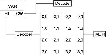
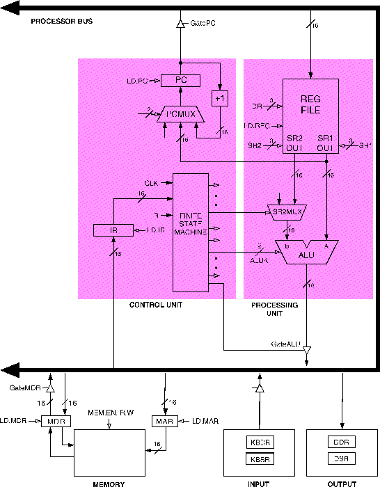
Place the address of the location to be read on the address bus via MAR.
Activate the memory read control signal on the control bus.
Wait for the memory to retrieve the data from the addressed memory location.
Read the data from the data bus into MDR.
Drop the memory read control signal to terminate the read cycle.
A simple Pentium memory read cycle takes 3 clocks:
Steps 1-2 and then 4-5 are done in one clock cycle each.
For slower memories, wait cycles will have to be inserted.
|
|
|
|
Place the address of the location to be written on the address bus via MAR.
Place the data to be written on the data bus via MDR.
Activate the memory write control signal on the control bus.
Wait for the memory to store the data at the addressed location.
Drop the memory write control signal to terminate the write cycle.
A simple Pentium memory write cycle takes 3 clocks:
Steps 1-2 and 4-5 are done in one clock cycle each.
For slower memories, wait cycles will have to be inserted.
Random access:
Accessing any memory location takes the same amount of time.
Volatility:
Volatile memory.
Needs power to retain the contents.
Non-volatile memory:
Retains contents even in the absence of power.
Basic types of memory:
Read-only memory, ROM.
Read/write memory, RAM.
ROM characterestics are:
Cannot be written into this type of memory.
Non-volatile memory
Most are factory programmed (i.e., written.)
Programmable ROMs (PROMs)
Can be written once by user
A fuse is associated with each bit cell
Special equipment is needed to write (to blow the fuse)
PROMS are useful:
During prototype development.
If the required quantity is small.
EROM characterestics are:
Can be written several times.
Offers further flexibility during system prototyping.
Can be erased by exposing to ultraviolet light.
Cannot erase contents of selected locations.
All content is lost on re-write.
Electrically erasable PROMs, or EEPROMs.
Contents are electrically erased.
No need to erase all contents
Typically a subset of the locations are erased as a group.
Most EEPROMs do not provide the capability to individually erase contents of a single location.
Commonly referred to as random access memory, RAM:
Volatile memories.
Two basic RAM types:
Static RAM, SRAM:
Retains data with no further maintenance.
Typically used for CPU registers and cache memory.
Dynamic RAM, DRAM:
A tiny capacitor is used to store one bit.
Due to leakage of charge, DRAMs must be refreshed to retain contents.
Read operation is destructive in DRAMs.
FPM DRAMs
FPM = Fast Page Mode
EDO DRAMs
EDO = Extended Data Out
Uses pipelining to speedup access
SDRAMs
Use an external clock to synchronize data output
Also called SDR SDRAMs (Single Data Rate)
DDR SDRAMs
DDR = Double Data Rate
Provides data on both falling and rising edges of the clock
RDRAMs
Rambus DRAM
add [eax], edx ; requires all phases of instruction cycle. add eax, 5 ; does not require Evaluate Address Phase mov eax, [myaddress] ; does not require the Execution Phase
Instructions are executed in sequence, second instruction follows the first, and so on.
Arithmetic, logic, and data movement instructions follow this criteria.
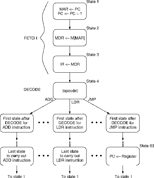
Another type of instruction, control instruction, changes sequence of instruction execution.
Control instructions change PC, (Instruction Pointer register EIP on 32-bit Intel x86 platforms) during the Execute Phase of the Instruction Cycle.
New value for PC is obtained during Fetch Phase from the instruction operand.
As soon as new instructions cycle begins, next instruction to fetch will be obtained at the new PC address.
Let's assume that register EAX stores a memory offset.
The memory offset is a 32-bit absolute value, which can be added or subtracted from the current address of program execution found in the instruction pointer EIP.
Consider x86 JMP instruction:
jmp eax
The JMP transfers control to the new address by modifying the program counter:
EIPnew = EIPcurrent + EAX.
The result of this operation is unconditional jump to a new address in the program.
Opcode of this x86 instruction is 0FFh.
|
|
|
|
A CPU that uses microcode has a collection of internal scratchpad registers that are not directly accessible outside of the CPU.
Simple circuits, such as an adder, wired together, are part of the microcode.
Machine language instructions do have access to the scratchpad registers.
Although microcode resembles machine language, there are many differences:
Micro-instructions typically rely on bits that directly control circuits,
such as master-slave flip-flop.
No program counter is required: each instruction is hardwired to the next instruction.
In general, micro-programming is more complex than assembly language programming.
An idea of a general-purpose programmable computing device, such as traffic danger sign discussed earlier, could be implemented by universal Turing Machine:
|
|
This idea still exists in modern computer design with low-level microcode, which directs the reading and decoding of higher level machine code instructions.
|
|
|
|
Single stream of instructions, sequenced by instruction counter.
Instructions stored with data in addressable memory.
Instructions encoded as numbers and are modifiable by arithmetic operations.
Radix 2 (binary) storage and math.
Word length is long enough for scientific computation.
Single address instructions, or single operand instructions, means that single, well-defined operations use exactly one memory address in combination with a register operand or immediate data.
See also: Wikipedia article about