3-550
INSTRUCTION SET REFERENCE
PSLLW/PSLLD/PSLLQPacked Shift Left Logical
Description
These instructions shift the bits in the data elements (words, doublewords, or quadword) in the
destination operand (first operand) to the left by the number of bits specified in the unsigned
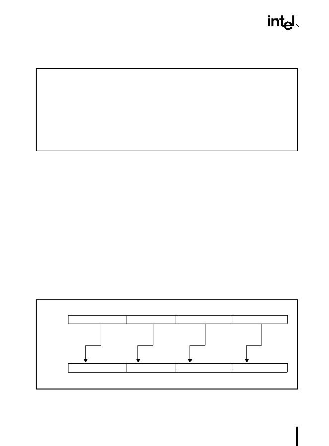
count operand (second operand) (refer to Figure 3-77). The result of the shift operation is written
to the destination operand. As the bits in the data elements are shifted left, the empty low-order
bits are cleared (set to zero). If the value specified by the count operand is greater than 15 (for
words), 31 (for doublewords), or 63 (for a quadword), then the destination operand is set to all
zeroes.
The destination operand must be an MMX technology register; the count operand can be
either an MMX technology register, a 64-bit memory location, or an 8-bit immediate.
The PSLLW instruction shifts each of the four words of the destination operand to the left by the
number of bits specified in the count operand; the PSLLD instruction shifts each of the two
doublewords of the destination operand; and the PSLLQ instruction shifts the 64-bit quadword
in the destination operand. As the individual data elements are shifted left, the empty low-order
bit positions are filled with zeroes.
Opcode
Instruction
Description
0F F1 /r
PSLLW mm, mm/m64Shift words in mm left by amount specified in mm/m64,
while shifting in zeroes.
0F 71 /6, ib
PSLLW
mm, imm8Shift words in mm left by imm8, while shifting in zeroes.
0F F2 /r
PSLLD mm, mm/m64Shift doublewords in mm left by amount specified in
mm/m64, while shifting in zeroes.
0F 72 /6 ib
PSLLD mm, imm8Shift doublewords in mm by imm8, while shifting in
zeroes.
0F F3 /r
PSLLQ mm, mm/m64Shift mm left by amount specified in mm/m64, while
shifting in zeroes.
0F 73 /6 ib
PSLLQ mm, imm8Shift mm left by Imm8, while shifting in zeroes.
Figure 3-77. Operation of the PSLLW Instruction
PSLLW mm, 2
mm
mm
1111111111111100
1111111111110000
0001000111000111
0100011100011100
shift left
shift left
shift left
shift left
3006026

