CIS-261 Home http://www.c-jump.com/bcc/c261c/CIS261syllabus.html

Memory Protection


  1. Memory Protection
  2. Segment Registers Revisited
  3. Segment Registers in Protected Mode
  4. Segment Start, Limit, and Status
  5. Segment Descriptor Data Structure
  6. Segment Descriptor Examples
  7. Segment Descriptor Cont.
  8. Segment Descriptor Cont.
  9. Segment Descriptor Cont.
  10. Segment Descriptor Types
  11. Mixed-Mode Operation
  12. Default Segments
  13. Paging and Address Translation Scheme
  14. Virtual to Physical Memory Mapping
  15. Intel 32-bit Address Translation Metrics
  16. Address Translation, Cont.
  17. Intel Memory Paging Summary

1. Memory Protection


2. Segment Registers Revisited


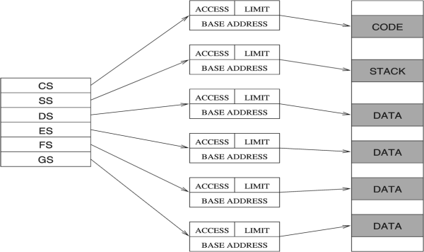
  • Segment Registers in Protected Mode separate different blocks of code and data to protect them from undesirable interactions.

  • CS (Code Segment) contains processor instructions and their immediate operands.

  • DS (Data Segment) normally contains data allocated by the program.

  • SS (Stack Segment) contains the program stack for use by PUSH, POP, CALL, and RET.

  • ES (Extra Segment) references secondary data segment. Used by string instructions.

  • FS, GS provide extra segments on 80386/486/Pentium.

  • The six segments of the memory system:
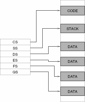
      The six segments of the memory system

    Segmented architecture is an important part of Linux and Windows memory-protection schemes.

3. Segment Registers in Protected Mode


  • Segment registers are called selectors when operating in protected mode.

  • In protected mode, segment registers simply point to data structures called segment descriptors that contain the information needed to access a physical memory location.

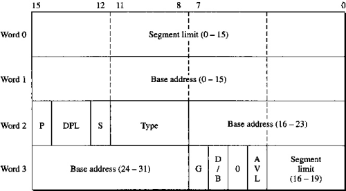
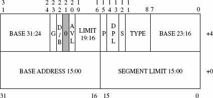
  • Every protected mode program must include a table of descriptors, which are 4-word data structures that defines the start and end of a segment.

  • A segment descriptor data structure:

      A segment descriptor


4. Segment Start, Limit, and Status


  • A typical segment descriptor contains the following information, packed into an 8-byte record:

    • Segment start: absolute 32-bit address of segment controlled by this descriptor

    • Segment limit: 20-bit field containing maximum address this segment can reference

    • Segment status: privilege level, segment present, segment available, segment type, etc.

  • Segment selector -> Segment descriptor -> Memory

      Protected Mode Architecture

      A segment descriptor


5. Segment Descriptor Data Structure


  • Access to memory is qualified by the descriptor selected by the current segment register.

  • Selector is a 12-bit number indicating which entry to use in the descriptor table:

    • If the selector is 0, the first descriptor is taken

    • Selector of 1 takes the second, etc.

  • The 80386 multiplies the selector by 8 (8 bytes per entry), and adds this to the base address of the table of descriptors (contained in an internal 386 register loaded by the programmer before switching to protected mode.)

  • Segment descriptor format:

      Segment descriptor format

      A segment descriptor


6. Segment Descriptor Examples


  • For example, a code fetch always uses the current CS value. A protected mode fetch starts by multiplying CS by 8 and then adding the descriptor base register. The 386 then reads an entire 8 byte record from the descriptor table. The entry describes the start of the segment; the processor adds the current instruction pointer to this start to get an effective address.

  • A data access behaves the same way. A load from location DS:1000 makes the processor read a descriptor by shifting DS left 3 bits (i.e., times 8), adding the table's base address (stored in the 386's on-board descriptor table register), and reading the 8 byte descriptor at this address. The descriptor contains the segment's start address, which is added to the offset in the instruction (in this case 1000). Offsets, and segment start addresses, are 32 bit numbers - it's really easy to reference any location in memory.

  • Segment descriptor format:

      Segment descriptor format

      A segment descriptor


7. Segment Descriptor Cont.


  • Segment Limit is a 20-bit value specifying the segment size:

    • if G = 0, 1 byte to 1 MB.

    • if G = 1, 4 KB to 4 GB, in increments of 4KB.

  • Base address is a 32-bit address of the segment start location.

  • G granularity bit indicates how segment size should be interpreted:

    • 0 = 64KB,

    • 1 = 4KB - 4GB(!).

  • DPL - 2-bit privilege level descriptor. Defines segment privilege level.

  • P - segment present in memory: yes/no

  • Segment descriptor format:

      Segment descriptor format

      A segment descriptor


8. Segment Descriptor Cont.


  • S = 1 identifies system segment, S = 0 if application CODE or DATA segment.

  • D/B - default CODE operand size, 0 = 16 bit, 1 = 32-bit. For DATA segments specifies stack mode - via SP or ESP:

  • For code segment, D bit is default size of operands and the offset value:

    • D = 0: 16-bit values

    • D = 1: 32-bit values

  • Segment descriptor format:

      Segment descriptor format


9. Segment Descriptor Cont.


  • AVL - available to the programmer.

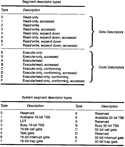
  • Type - 4-bit segment descriptor type attribute, see segment descriptor types .

  • For example,

    • Data segment: read-only, read-write, ...

    • Code segment: execute-only, execute/read-only, ...

  • Segment descriptor format:

      Segment descriptor format


10. Segment Descriptor Types


11. Mixed-Mode Operation


  • Pentium allows mixed-mode operation in the same program.

  • Possible to combine 16-bit and 32-bit operands and addresses

  • D/B bit indicates the default size:

    • 0 indicates 16 bit mode,

    • 1 if 32-bit mode.

  • Pentium also provides two override instruction prefixes:

    • 66h changes default operands size from 16-bit to 32-bit and vice versa.

    • 67h changes 32-bit address to 16-bit and vice versa.

  • Segment descriptor format:

      Segment descriptor format


12. Default Segments


13. Paging and Address Translation Scheme


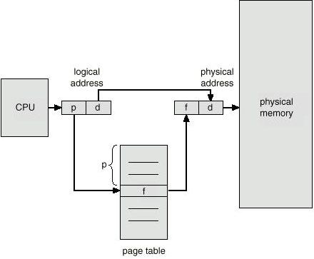
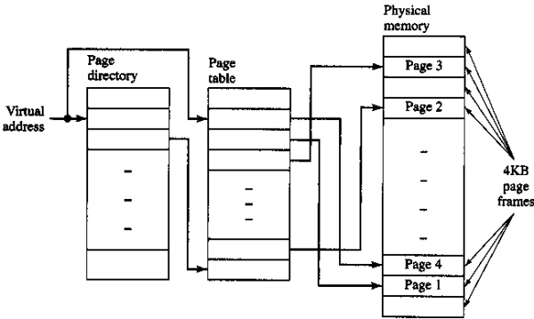
  • Memory Paging is yet another 386 feature that permits extending the address space far beyond 4 Gb.

  • Address generated by CPU (logical address) is divided into:

    1. Page number p is an index into a page table that contains base address of each page in physical memory.

    2. Page offset d is a displacement, combined with base address to define the physical memory address that is sent to the memory unit.

  • Memory paging:

      memory paging


14. Virtual to Physical Memory Mapping

memory paging Virtual to physical mapping

15. Intel 32-bit Address Translation Metrics


  • Maximum number of segments per process is 16K.

  • Each segment can be as large as 4 GB.

  • The page size is 4K.

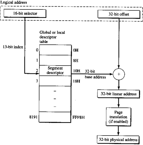
  • The logical address is a pair of 16-bit selector and 32-bit offset.

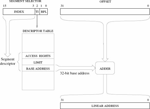
  • The segment selector is used to index the descriptor table to obtain the descriptor entry.

  • The 64-bit descriptor entry (8 bytes) has detailed information about the particular segment including the 32-bit base address and length of the logical segment.

  • Protected-mode address translation:

      Protected-mode address translation


16. Address Translation, Cont.


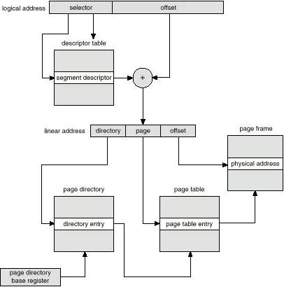
  • The 32-bit base address obtained from the descriptor entry is added to the memory offset to obtain a 32-bit linear address.

  • If virtual memory mode is enabled, the linear address of the segment is interpreted as a 20-bit page number and a 12-bit page offset.

  • The 386 uses a two-level paging scheme, thus dividing the page number into 10-bit page-table directory pointer and a 10-bit page table pointer.

Intel segment translation

17. Intel Memory Paging Summary


  •   memory paging Intel 386

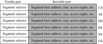
  • Visible and invisible parts of segment registers:

      Visible and invisible parts of segment registers

  • A segment descriptor:

      A segment descriptor