CIS-261 Home http://www.c-jump.com/bcc/

Digital Logic


  1. Digital Logic Structures
  2. Transistor Types
  3. The MOS Transistor
  4. N-type Transistor
  5. P-type Transistor
  6. CMOS circuits
  7. Logic Gates
  8. The NOT Gate - Inverter
  9. NOR gate
  10. OR gate
  11. AND gate
  12. Basic Logic Gates
  13. DeMorgan's Law
  14. Larger Gates
  15. Combinational Logic Circuits
  16. Two-level Multiplexer
  17. Mux Example
  18. Four-input Multiplexer
  19. The 1-to-2 Line Demultiplexer
  20. Decoder

1. Digital Logic Structures


2. Transistor Types


  • BJT stands for bipolar junction transistor.

  • BJT transistors are used primarily in amplifying or switching applications (e.g. power supplies.)

  • FET stands for the field-effect transistor.

  • FET transistors rely on an electric field to control conductivity of a channel.

  • JFET stands for the junction gate field-effect transistor (or JUGFET), and is the simplest type of the field effect transistor.

  • See also: wikipedia articles about transistors and JFET transistors.

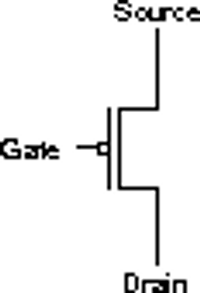
  • Common transistor circuit symbols:

    PNP P-channel
    NPN N-channel
    BJT JFET

3. The MOS Transistor


  • Most CPUs are made of MOS transistors.

  • MOS stands for is metal-oxide semiconductor.

  • MOSFET is most commonly used type of FET, the field-effect transistor. The MOSFET has the advantage over JFET because of MOSFET's extremely low gate current (measured in picoamperes.)

  • MOSFET transistors operate logically, just like wall switches.

  • Transistor has three terminals:

    • Gate terminal is controlling the opening and closing of a physical gate.

    • Source

    • Drain

  • Electrons flow from the source terminal towards the drain terminal.

  • See also: wikipedia article about field effect transistor

  • Common MOSFET circuit symbols:

      MOSFET transistor JFET N-type transistor

4. N-type Transistor


  • When source and drain are connected like piece of wire we have a closed circuit between the source and the drain.

    • This happens when the gate is supplied 2.9 volts.

  • When connection between source and the drain is broken, we say it is an open circuit.

    • This happens when the gate is supplied with 0 volt

  • Common N-type transistor circuit symbols:

      JFET N-type transistor JFET N-channel transistor

5. P-type Transistor


  • Works in exactly the opposite fashion from the N-type transistor.

  • When gate is supplied with 0 volts, we have closed circuit like a wire between the source and the drain.

  • When the gate is supplied 2.9 volts, P-type transistor acts like an open circuit with broken connection.

  • Common P-type transistor circuit symbols:

      JFET P-channel transistor

6. CMOS circuits


7. Logic Gates


8. The NOT Gate - Inverter


  • Includes two MOS transistors.

  • The circle in the NOT-gate symbol on circuit drawings is called an inversion bubble.

  • A bubble on the input or output wire of another circuit symbol indicates an inversion of that signal:

    • 0 becomes 1, and vice versa.

  •   NOT Gate inverter

9. NOR gate


  • Schematic circuit based on 4 transistors.

  • See also: basic gates

  •   NOR gate

10. OR gate


  • OR gate is constructed by adding an inverter to the NOR gate.

  • See also: OR gate

  •   OR gate

11. AND gate


  •   AND gate

12. Basic Logic Gates


  • Instead of drawing individual transistors, we will draw abstract symbols representing various types of gates as shown:

13. DeMorgan's Law


  •      _______
         _     _
         A AND B   =  A OR B
    
  • In plain English this is

    • "The outcome is true when
      it is not the case that both A and B are false."

  • The law is equivalent to

    • "The outcome is true when
      at least one of A and B is true."

  • The relationship is also called De Morgan duality:

        not (P and Q) = (not P) or (not Q)
        not (P or Q) = (not P) and (not Q)
    

14. Larger Gates


  • Multiple inputs can be combined into a single unit of AND, OR, NAND, and NOR gates.

  • The truth table can be constructed without a problem as well:

  •   three input AND gate

15. Combinational Logic Circuits


16. Two-level Multiplexer


  • Mux is a two-level (two-input) multiplexer.

  • It's function is to select one of the inputs and connect it to the output.

  • Input A is the addressing input, specifying which of the two data inputs, X0 or X1, will be transmitted to the output X.

  • See also: two input multiplexer

  •   two input multiplexer

17. Mux Example


  • S is a selector signal.

  • If S = 0 then the output is identical to input A.

  • If S = 1 then the output is identical to input B.

  •   mux

18. Four-input Multiplexer


  • Multiplexers are not limited to two data inputs.

  • If two addressing inputs used, we can multiplex up to four data signals.

  • With three addressing inputs, we can multiplex eight signals, and so on.

  • Four-input multiplexer is a digital circuit that combines four input signals, one of which is selected by two separate address inputs to be sent to the single output.

  •   four-input multiplexer

  • The number of signal inputs is equal to 2k, where k is the number of addressing inputs.

  • As the number of inputs increases, so is the number of selectors that are required for the mux to operate.

19. The 1-to-2 Line Demultiplexer


  • The opposite of the multiplexer circuit, logically enough, is the demultiplexer.

  • The one-input demultiplexer circuit takes

    • one single data input IN, and

    • one (or more) address selector inputs A.

  •   two-line decoder

20. Decoder


  • The demultiplexer circuit can be transformed into a decoder.

  • The decoder determines type of the input bit pattern, therefore it is a circuit useful to interpret bit patterns.

  • Address inputs A and B specify a binary number.

  • The output matches the specified binary address input as follows:

    • only one single output is set to 1, while the rest of the outputs are 0s.

  • An example of a bit pattern would be an OPCODE that specifies the type of the CPU instruction.

  •   two input decoder


  • If the number of addressing inputs (A, B, ...) is equal to k, then the number of output lines becomes 2k.