6-21
INSTRUCTION SET SUMMARY
Table 6-4 shows the mnemonics for the CMOVcc instructions and the conditions being tested
for each instruction. The condition code mnemonics are appended to the letters CMOV to
form the mnemonics for the CMOVcc instructions. The instructions listed in Table 6-4 as pairs
(for example, CMOVA/CMOVNBE) are alternate names for the same instruction. The assem-
bler provides these alternate names to make it easier to read program listings.
The CMOVcc instructions are useful for optimizing small IF constructions. They also help elim-
inate branching overhead for IF statements and the possibility of branch mispredictions by the
processor.
These instructions may not be supported on some processors in the Pentium
®
Pro processor
family. Software can check if the CMOVcc instructions are supported by checking the
processors feature information with the CPUID instruction (refer to CPUIDCPU Identifica-
tion in Chapter 3, Instruction Set Reference of the Intel Architecture Software Developers
Manual, Volume 2).
6.3.1.3.EXCHANGE INSTRUCTIONS
The exchange instructions swap the contents of one or more operands and, in some cases,
performs additional operations such as asserting the LOCK signal or modifying flags in the
EFLAGS register.
The XCHG (exchange) instruction swaps the contents of two operands. This instruction takes
the place of three MOV instructions and does not require a temporary location to save the
contents of one operand location while the other is being loaded. When a memory operand is
used with the XCHG instruction, the processors LOCK signal is automatically asserted. This
instruction is thus useful for implementing semaphores or similar data structures for process
synchronization. (Refer to Section 7.1.2., Bus Locking of the Intel Architecture Software
Developers Manual, Volume 3, for more information on bus locking.)
The BSWAP (byte swap) instruction reverses the byte order in a 32-bit register operand. Bit
positions 0 through 7 are exchanged with 24 through 31, and bit positions 8 through 15 are
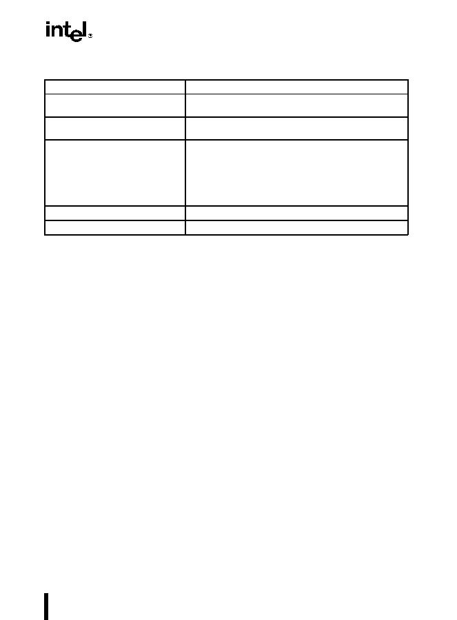
Table 6-1. Move Instruction Operations
Type of Data Movement
Source
>
Destination
From memory to a register
Memory location
>
General-purpose register
Memory location
>
Segment register
From a register to memory
General-purpose register
>
Memory location
Segment register
>
Memory location
Between registers
General-purpose register
>
General-purpose register
General-purpose register
>
Segment register
Segment register
>
General-purpose register
General-purpose register
>
Control register
Control register
>
General-purpose register
General-purpose register
>
Debug register
Debug register
>
General-purpose register
Immediate data to a register
Immediate
>
General-purpose register
Immediate data to memory
Immediate
>
Memory location

