B-36
INSTRUCTION FORMATS AND ENCODINGS
B.5.FLOATING-POINT INSTRUCTION FORMATS AND
ENCODINGS
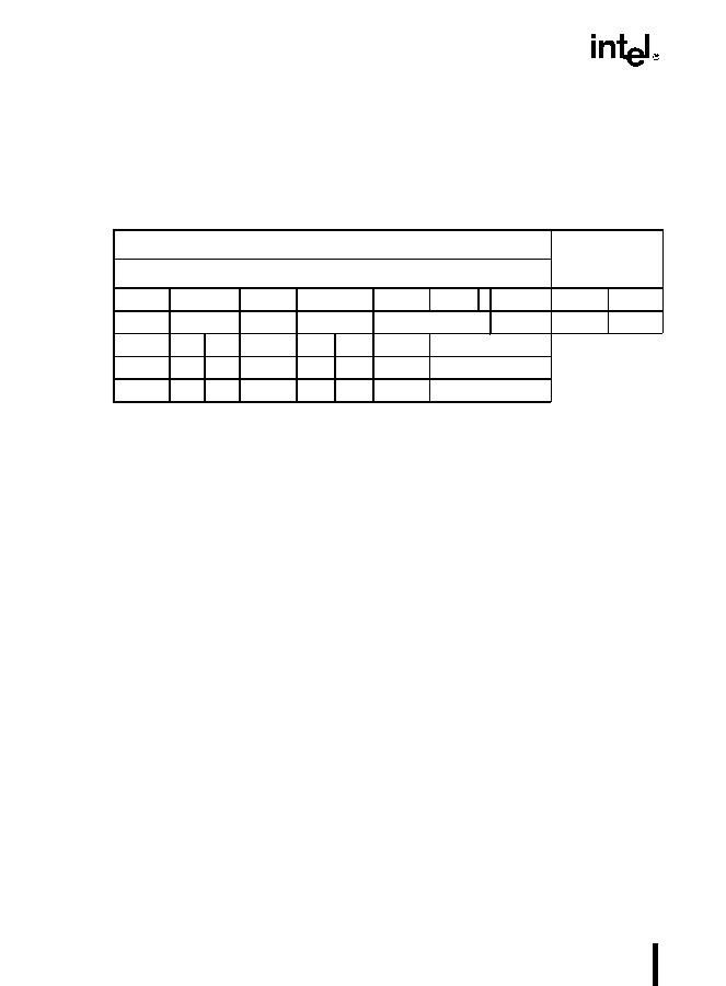
Table B-22 shows the five different formats used for floating-point instructions In all cases, in-
structions are at least two bytes long and begin with the bit pattern 11011.
MF = Memory Format
00 32-bit real
01 32-bit integer
10 64-bit real
11 16-bit integer
P = Pop
0 Do not pop stack
1 Pop stack after operation
d = Destination
0 Destination is ST(0)
1 Destination is ST(i)
R XOR d = 0 Destination OP Source
R XOR d = 1 Source OP Destination
ST(i) = Register stack element i
000 = Stack Top
001 = Second stack element
?
?
?
111 = Eighth stack element
The Mod and R/M fields of the ModR/M byte have the same interpretation as the corresponding
fields of the integer instructions. The SIB byte and disp (displacement) are optionally present in
instructions that have Mod and R/M fields. Their presence depends on the values of Mod and
R/M, as for integer instructions.
Table B-23 shows the formats and encodings of the floating-point instructions.
Table B-22. General Floating-Point Instruction Formats
Instruction
First Byte
Second Byte
Optional Fields
111011OPA
1
mod
1OPBr/ms-i-bdisp
211011MFOPAmod
OPB
r/ms-i-bdisp
311011dPOPA11OPBRST(i)
411011001111
OP
511011011111
OP
1511109876543210

