7-9
FLOATING-POINT UNIT
whereas, the Pentium
®
processor has two integer units and one FPU, and the Intel486
processor has one integer unit and one FPU.)
The instruction execution environment of the FPU (refer to Figure 7-5) consists of 8 data regis-
ters (called the FPU data registers) and the following special-purpose registers:
The status register.
The control register.
The tag word register.
Instruction pointer register.
Last operand (data pointer) register.
Opcode register.
These registers are described in the following sections.
7.3.1.FPU Data Registers
The FPU data registers (shown in Figure 7-5) consist of eight 80-bit registers. Values are stored
in these registers in the extended-real format shown in Figure 7-17. When real, integer, or
packed BCD integer values (in any of the formats shown in Figure 7-17) are loaded from
memory into any of the FPU data registers, the values are automatically converted into
extended-real format (if they are not already in that format). When computation results are
subsequently transferred back into memory from any of the FPU registers, the results can be left
in the extended-real format or converted back into one of the other FPU formats (real, integer,
or packed BCD integers) shown in Figure 7-17.
The FPU instructions treat the eight FPU data registers as a register stack (refer to Figure 7-6).
All addressing of the data registers is relative to the register on the top of the stack. The register
number of the current top-of-stack register is stored in the TOP (stack TOP) field in the FPU
status word. Load operations decrement TOP by one and load a value into the new top-of-stack
register, and store operations store the value from the current TOP register in memory and then
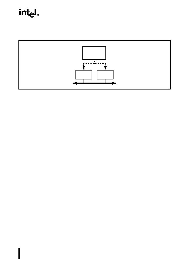
Figure 7-4. Relationship Between the Integer Unit and the FPU
Instruction
Data Bus
Decoder and
Sequencer
FPU
Integer
Unit

