E-6
GUIDELINES FOR WRITING FPU EXCEPTIONS HANDLERS
*
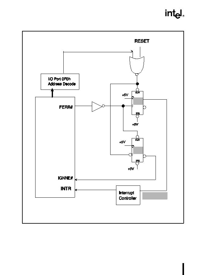
In the circuit in Figure E-1, when the FPU exception handler accesses I/O port 0F0H it clears
the IRQ13 interrupt request output from Flip Flop #1 and also clocks out the IGNNE# signal
(active) from Flip Flop #2. So the handler can activate IGNNE#, if needed, by doing this 0F0H
access before clearing the FPU exception condition (which de-asserts FERR#). However, the
Figure E-1. Recommended Circuit for MS-DOS* Compatibility FPU Exception Handling
Intel486
?
,
Pentium
®
, or
Pentium Pro
processor
FF #1
FF #2
FP_IRQ
Legend:
FF #n Flip Flop #n
CLR Clear or Reset

